.
Using an Existing Low Power Transmitter as an RF Source
A 2 phase Analog to Digital Converter for 80 and 160 Meters
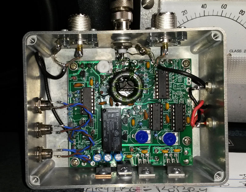
Analog to Digital Converter built by K1KBW
This Analog to Digital converter is simple to build and is quite stable.
The same circuitry used in the VFO (shown elsewhere on this site) is used
for the Analog to Digital converter.
In essence, the A to D converter takes approximately 1 to 2 watts of RF at
the desired operating frequency, and produces a 2 phase, 12V digital RF output
suitable for driving the class E transmitters show on this site.
The A to D converter includes RF waveform duty-cycle control
(allows adjustment of the
pulse width of the "on" pulse), facilitating maximum efficiency
in the class E RF amplifier, and providing a means of adjusting the balance
between modules in single ended push pull class E amplifiers.
Schematics:
A to D Converter Schematic (.PDF)
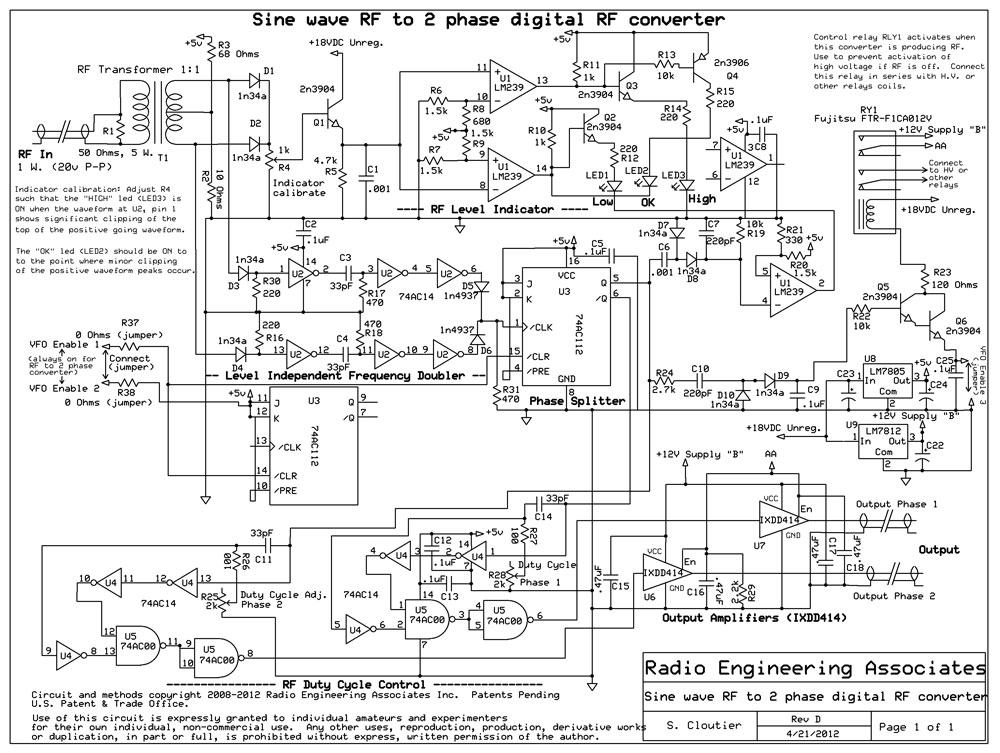
Circuit Details
Referring to the Schematic, RF is fed to the converter through a small RF
transformer wound on a single FB-43-1020 core or similar. The RF is then
rectified, and fed to a level sensing ciruit to let the operator know when
the RF level fed to the device is correct. Indictors LEDs will show either a
too-low level, OK level, or a too-high level. Always adjust the RF source
feeding the converter for the proper (OK) level.
RF is also sent to a frequency doubler circuit. The output from the frequency
doubler is then divided by 2 by a J-K flip flop. The
flip flop will change state on each rising edge of the doubler output
signal. By doubling and dividing the input signal, we will guarantee a symmetrical,
two phase output waveform of equal duty cycle in each phase.
The two divider outputs feed simple pulse shaping circuits, allowing adjustment of
the duty cycle ("on time") of the output waveform for each
phase. From the pulse
shaping circuitry, the RF signals are fed to two IXDD614 or IXDD414 driver ICs,
providing a 12V, low impedance output suitiable for driving terminated
(50 ohm) coax cable.
The A to D Converter includes a relay that can be used to enable the operation of other
circuits or relays. When the Converter is producing output, the relay closes. When
the Converter is not producing output, the relay will open.
Ideally, the Converter relay should be used to prevent the high voltage
power supply from supplying power, should the converter not be receiving RF
for whatever reason. This is a very good safety measure, and should be
implemented as part of any transmitter using this system.
Note: The Converter relay should not be
the only source of control for the high voltage supply, rather the relay should be
in series with the coil of the high voltage power supply control relay(s) as
ONE of the conditions for high voltage supply operation.
|
The Converter should be constructed in a good, shielded enclosure. An aluminum
or copper enclosure should be used, and all leads such as power, or indictors
should be well bypassed, preferably using feed-through insulators, to prevent
any stray RF from entering getting to the very sensitive A to D converter circuitry.
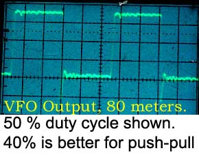 Use an oscilloscope to verify
that both outputs are functioning. Adjust R17 and R19 to obtain the desired
on-time duty cycle. A good duty cycle for push-pull or single ended push-pull
is 40% on, 60% off. Once connected to an operating class E RF amplifier,
the duty cycle can be further adjusted to obtain optimum efficiency,
and balance between modules (if more than one RF module is used).
Use an oscilloscope to verify
that both outputs are functioning. Adjust R17 and R19 to obtain the desired
on-time duty cycle. A good duty cycle for push-pull or single ended push-pull
is 40% on, 60% off. Once connected to an operating class E RF amplifier,
the duty cycle can be further adjusted to obtain optimum efficiency,
and balance between modules (if more than one RF module is used).
|